The engine from the washing machine and its connection to the network
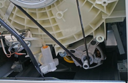
The motor is the heart of the washing machine. This device rotates the drum during washing. In the first models of machines, belts were attached to the drum, which acted as drives and ensured the movement of the container filled with laundry. Since then, developers have noticeably improved this unit, which is responsible for turning electricity into mechanical work.
There are currently three types of motors used in the production of washing equipment.
Types
Asynchronous .
Motors of this type consist of two parts - a stationary element (stator), which serves as a supporting structure and serves as a magnetic circuit, and a rotating rotor, which drives the drum. The motor rotates as a result of the interaction of the alternating magnetic field of the stator and the rotor. This type of device is called asynchronous because it is not able to reach the synchronous speed of the rotating magnetic field, but follows it, as if catching up.
Asynchronous motors are found in two versions: they can be two-phase and three-phase. Two-phase models are rare today, because at the threshold of the third millennium, their production has practically ceased.
The weak point of such a motor is the weakening of the torque. Outwardly, this is manifested by the violation of the trajectory of the drum movement - it wobbles, not making a full rotation.
The undoubted advantages of asynchronous type devices are the uncomplicated design and ease of maintenance, which consists in the timely lubrication of the motor and replacement of faulty bearings. The asynchronous motor is not loud, and it costs quite cheap.
The disadvantages of the device include its large size and low efficiency.
Usually, these motors are equipped with simple and inexpensive models, which are not characterized by high power.
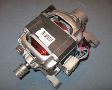
Collector
Collector motors have replaced two-phase asynchronous devices. Three-quarters of household appliances are equipped with motors of this type. Their peculiarity is the ability to operate from both alternating and direct current.
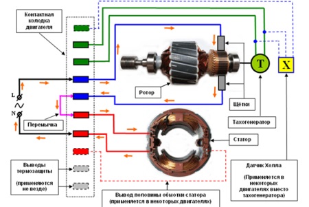
To understand the principle of operation of such a motor, let us briefly describe its device. The collector is a copper drum divided into even rows (sections) by insulating "dividers". The contact points of these sections with external electric circuits (the term "leads" is used in electrical engineering to designate such sections) are diametrically located on opposite sides of the circumference. The two brushes, the sliding contacts which ensure the interaction of the rotor with the motor, are in contact with the leads, one on each side. As soon as any section is energized, a magnetic field appears in the coil.
When the stator and rotor are energized directly, the magnetic field begins to rotate the motor shaft in a clockwise direction. This happens because of the interaction of charges: the same charges repel, different charges attract (for more clarity, remember the "behavior" of conventional magnets). The brushes gradually move from one section to another - and the movement continues. This process is not interrupted as long as there is voltage in the network.
In order to direct the shaft counterclockwise, it is necessary to change the distribution of charges on the rotor. To do this, the brushes are switched in the opposite direction - towards the stator. Usually, miniature electromagnetic starters (power relays) are used for this purpose.
Among the advantages of the collector motor - high speed of rotation, smooth change of rotation frequency, which depends on the change of voltage, independence from the frequency of power supply fluctuations, high starting torque and compactness of the device. Among its disadvantages is a relatively short service life due to the rapid wear of the brushes and the collector. Friction causes a significant increase in temperature, resulting in the destruction of the layer that insulates the collector contacts. For the same reason, an interwinding fault can occur in the winding, which can cause a weakening of the magnetic field. An external manifestation of such a malfunction will be a complete stop of the drum.
Inverter motor (non-collector motor)
The inverter motor is a direct-drive motor. This invention is just over 10 years old. Developed by the famous Korean concern, it quickly gained popularity due to its long service life, reliability, wear resistance and its very modest size.
The components of this type of motor are also the rotor and stator, but the fundamental difference is that the motor is attached to the drum directly, without the use of connecting elements, which fail in the first place.
Among the undoubted advantages of inverter motors are simplicity, the absence of parts subject to rapid wear, convenient location in the body of the machine, low noise and vibration, compactness.
The disadvantage of such a motor is labor intensity - its production requires a lot of cost and effort, which is noticeably reflected in the price of inverter machines.
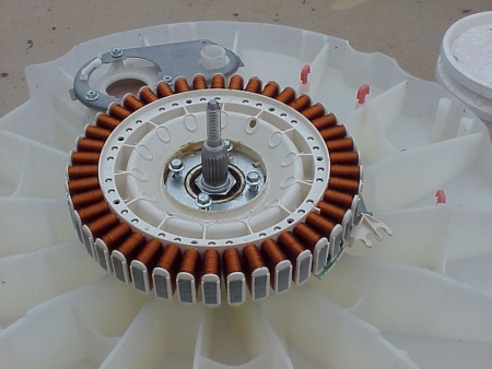
Diagram of connection of the motor to the mains
Modern washing machine
When connecting the motor of a modern washing machine to the network with a voltage of 220V, it is necessary to take into account its main features:
- it works without a starting winding;
- to start the motor does not need a starting capacitor.
To start the motor, it is necessary to connect a certain way to the mains going from it. Below are the wiring diagrams for collector and commutatorless motors.
First of all, determine the "front of work" by excluding the contacts that come from the tachogenerator and are not involved in the connection. They are recognized by means of a tester working in the ohmmeter mode. Having fixed the tool on one of the contacts, with the other probe look for its paired terminal. The resistance value of the tachogenerator wires is about 70 ohms. To find the pairs of the remaining pins, call them in the same way.
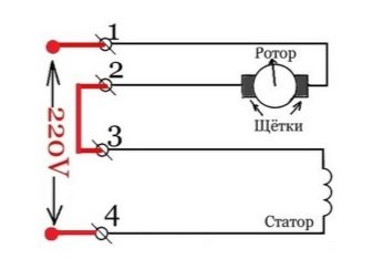
Now let's move on to the most important stage of the work. Connect a 220V wire to one of the winding outputs. Connect the second output to the first brush. Connect the second brush to the remaining 220V wire. Plug the motor into the mains to check its operation*. If you have made no mistakes, the rotor will start to rotate. Keep in mind that with this connection it will only move in one direction. If the test run went smoothly, the unit is ready for operation.
To reverse the direction of movement of the motor, the connection of the brushes must be reversed: now the first will be plugged in and the second will be connected to the output of the winding. Check that the motor is ready for operation as described above.
You can visually see the connection process in the following video.
An older model washing machine
With the connection of the motor in old-style machines, the case is more complicated.
First, identify the two matching pairs of terminals. To do this, use a tester (aka multimeter). Fixing the tool on one of the winding pins, use the other probe to find the pin paired to it. The remaining pins will automatically form the second pair.
Then determine where the start winding and the work winding are located. Measure their resistance; a higher resistance will indicate the start winding (SW), which creates the initial torque, a lower resistance is characteristic of the excitation winding (EW), which creates the magnetic field of rotation.
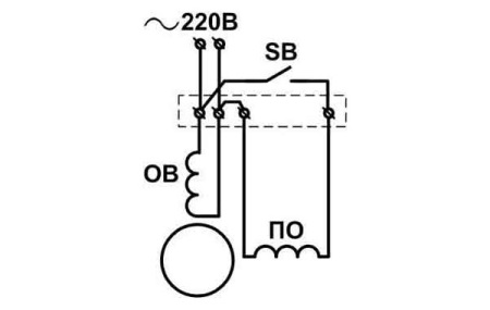
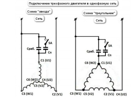
Below are possible wiring diagrams for a three-phase induction motor, and a detailed video tutorial for them.